BraceBolt Sheer Test
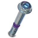 Shear Test for Brace Panel Bolts
BraceBolt testing was carried-out by Melbourne Testing Services personnel at Mulgrave, Victoria
Testing Procedure
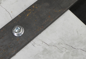
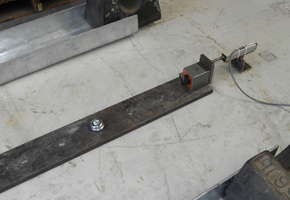
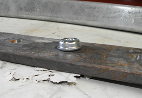
Tested as per AS3850. Installation was by drilling a noninal 20mm diameter hole into a concrete test block cast from 20 Mpa concrete. The anchors were installed through a 20 mm thick steel shear plate to represent the maxmium allowable thickness of a brace foot and trightened to the specified torque of 150Nm with a calibrated torque wrench
Shear test load was then applied until failure of the anchor connection occurred and the peak test load was recorder.
Warning
Minimum edge distance for the BraceBolt set concrete is 200mm
regardless of the strength of the concrete.
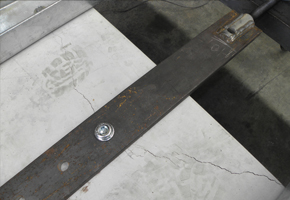
200mm Distance Test
In the case of the 200mm edge distance, cracking of the concrete forward of the bolt governed the mode of failure Post-test examination of the bolt did not reveal any significant plastic deformation (distortion) or sign of failure.
The peak test forces recorder during shear testing of the Bracebolt Panel Bolts were:
89kN ≈9t for the 200mm edge distance test.
As per AS3850 use a reduction of k2 = 0.70 for steal failure and k2= 0.65 for concrete.
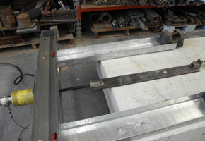
500mm Distance Test
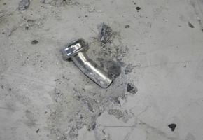
In the case of the 500mm edge distance test, the bolt was observer to partially withdraw from the concrete before final failure which occurred by tensile rupture of the threaded portion of the bolt. There was no cracking in the concrete odserved in this case.
The peak test forces recorder during shear testing of the Bracebolt Panel Bolts were:
98kN ≈10t for the 500mm edge distance test.
As per AS3850 use a reduction of k2 = 0.70 for steal failure and k2 = 0.65 for concrete.
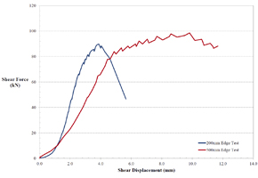
Test Data
Test data curves for the two Brace Panel Bolt shear tests are provided:
Page 1 of 1
![]() Shear Test for Brace Panel Bolts
Shear Test for Brace Panel Bolts


